How to use the sample
Material stiffness:
The stiffness of a plastic part is determined by the combination of the material’s tensile modulus (Young’s modulus) and the part’s geometry. In case of plastics, the tensile moduli generally varies between 1 and 4 GPa (non-reinforced) and 8 and 20 GPa (glass-reinforced). For aluminium and steel, the values are 70 GPa and 210 GPa, respectively. The importance of geometry is therefore emphasized in plastic design.
The stiffness of a plastic part is greatly influenced by its wall thickness. The wall thickness of the sample is 2 mm, which is quite typical for a plastic part. The relative stiffness of a plastic material can be tested by pressing the tab in the middle of the sample. Does it bend easily (compared with other plastics)? Another good test for sample stiffness is knocking on its edge (an eraser is a good tool for this). The higher the sound, the higher the tensile modulus. You can also twist or bend the sample to test stiffness.
Density and overall impression:
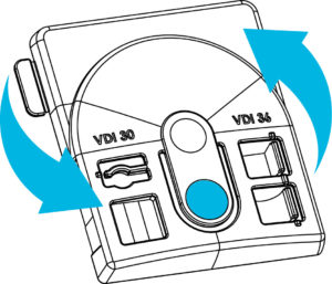
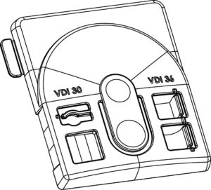
The volume of the sample mould cavity is 19.61 cm3. The samples are in fact slightly smaller, depending on material-specific shrinkage. Plastic density varies between 0.9 and 1.5 g/cm3. The weight of the samples therefore varies between 18 and 30 grams. The difference between the lighter and heavier samples can be felt by hand; the weight is often proportional to the material stiffness.
Plastic grades differ by the feel of their surface: sticky or slippery, wax-like or dry, hard or soft.
The sound that the sample makes when you knock on its edge will tell you something about sample stiffness and indicates the type of material used. Glass-reinforced plastics make somewhat clanging sounds, while amorphous materials tend to sound rattly.
A rough guess of a plastic product’s material can often be made after knocking on its side.
Integral hinge:
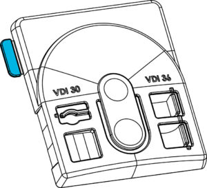
Some plastic grades allow utilisation of so-called integral hinge. Thus, for example, the lid and base of a box can be manufactured as one piece.
Toughness, plasticity, and fluidity are required from the material for the hinge to function.
There is a small tab at the upper left corner of the sample. By bending this tab, you can determine whether the material is suitable for making the integral hinge.
If the tab is missing, the material fluidity has been insufficient to allow filling through the hinge.
Integral hinges are used most often with non-reinforced polyolefins (PP and PE).
The hinge may also be functional when using some other plastic grades, such as PA or POM.
Surface quality:
In general, plastic components very closely replicate the surface of the mould cavity,
but the impression varies between different plastic grades.
The sample comes with five different surface qualities:
- Moderate spark-eroded surface: VDI 30
- Rather rough spark-eroded surface: VDI 36
- Well-polished surface: SPI-A1
- Sand-blasted surface: approx. VDI 21 or SPI-D2
- Non-finished machined surface
By comparing the samples, you can see how surface qualities appear in different materials
and the effect of fibreglass reinforcement.


Plastic fluidity:
Plastic fluidity is expressed with ‘melt flow index’ and ‘viscosity’, which are inversely proportional. Materials with high melt flow index and low viscosity are very fluid, pass through the narrowest of gaps, and fill the smallest pockets in the mould cavity. On the other hand, they also find their way between parting surfaces, which results in flash formation.
Material fluidity should be considered when choosing the raw material.
The sample has a window divided into nine small panes. The pane thickness increases by 0.05 mm intervals, with the maximum value at 0.45 mm. Material fluidity can be determined based on the filling of the window. If only a few of the panes have been filled, the melt flow index is low – and vice versa.
It is possible to adjust the melt flow index by raw material blends, but this can also affect other properties.

Plastic shrinkage:
Depending on the plastic grade, the samples are from 0.2% to 2.5% smaller than the mould cavity,
due to plastic shrinkage upon cooling. In the case of semi-crystalline plastics, the shrinkage is slightly smaller parallel to flow than perpendicular to flow. The same applies to glass-reinforced materials.
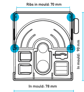
The samples have been manufactured using the same mould cavity, so the difference in size is directly proportional to the material shrinkage. At the bottom side of the sample, there are two pairs of ribs – in the mould, the exact distance between these ribs is 70 mm. If a clear difference is measurable between them, the extent of shrinkage differs by flow direction.
Sensitivity to sink marks:
Thicker wall sections (compared with general wall thickness) continue to cool and shrink even after the surrounding material has already set. This is reflected in the ‘sink marks’ on the product surface.
Rib and boss bases are sensitive to sink mark formation. Sink mark visibility can be reduced by adjusting surface roughness, and its extent by adjusting rib thickness. The common rule-of-thumb for rib thickness value is 0.6 x wall thickness, but this varies from one material to another.
There are three different surface finishes in the sample, each with three ribs of different thicknesses. This allows determination of the material’s sensitivity to sink marks.


Warpage:
The goal of good plastics design is to ensure that the mould fills and cools down as evenly as possible.
A common problem is that the tool fails to conduct the heat away from the product’s inner corners as efficiently as from the other parts. The corners continue to shrink even after the surrounding material has already set. This results in product warpage; the phenomenon is often referred to as the corner effect.
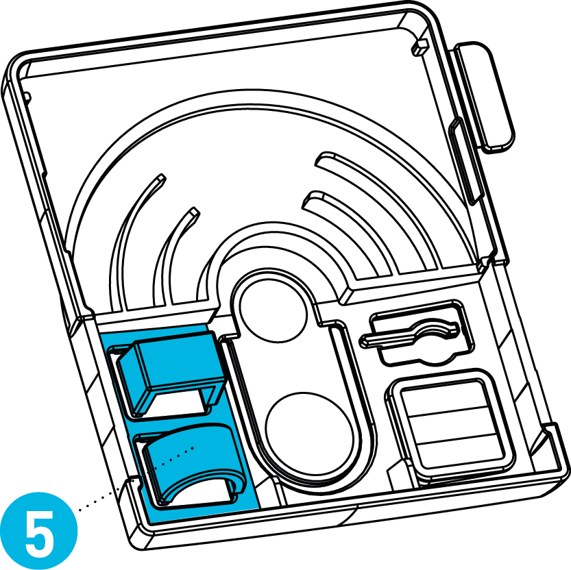
Sensitivity to such distortions is material-specific. The sample comes with two curved elements (1,2) for warpage sensitivity assessment. The rounded arc (2) represents better plastics design; it should differ from the mould geometry insignificantly or not at all. In case of the angular element (1), more inwards warpage is likely. In addition to this, there are two ribs (3) supporting the rear edge of the item. If the edge is wavy, the material is sensitive to warpage.
The general straightness of the sample also tells a lot about the material’s sensitivity to warpage.


Draft angle vs.surface roughness:
Plastic components should preferably have some draft.
This allows avoiding product scratches, process problems, and extended cycle times.
The required draft angle varies depending on the material and surface roughness.
The left and right side of a sample represent different surface roughness.
VDI 30 represents moderate spark-eroded surface, while VDI 36 is already quite rough.
Both sides of the sample have an area with three different draft angles: 0.5, 1, and 2 degrees.
If scratches are visible on some of these surfaces, it can be concluded that the draft angle/surface roughness combination is unfavourable for the used material.
From a technical point of view, the draft angle can never be too large.
No risks should be taken in this respect without good reason.

Creep and stress corrosion:
Creep refers to a phenomenon in which an item distorted for a long time never recovers its original shape. Creep is affected by time, temperature, stress – and, naturally, material. All plastics are susceptible to creep to some extent. Semi-crystalline materials are less sensitive – in particular, POM is known for its low level of creep. The phenomenon must always be considered when designing plastic springs, snap-fits,
and press fits.
The sample comes with a small indicator for checking the material’s sensitivity to creep.
The indicator can be deflected from its original position, e.g. by forcing the head of a machine screw or a drill bit under it. How close to its original position will the indicator return after one week?
If the indicator breaks or comes loose, this is caused by a phenomenon referred to as ‘stress corrosion’. Above all, this problem plagues amorphous materials, but should be considered universally in all plastic design. Solvents and fats accelerate stress corrosion and often trigger its effects.
A cracked boss is a typical manifestation of stress corrosion.

Friction:
Materials differ by friction properties. Semi-crystalline polymers such as POM and PA are known as excellent bearing materials. In many cases, secure gripping of the product by hand is desired.
To some extent, this can be influenced by surface roughness. But rougher surface does not necessarily mean higher friction: A polished surface is sometimes more secure than a rough surface.
Adding fibreglass to plastic will not improve the friction properties, but it also won’t fully eliminate them.
The sample demonstrates the material feel with different surface qualities.
You can also test the sample by rubbing it against metal or another sample
