Here is a comprehensive list of Tg's for various thermoplastics.
Category: Article
How to use the sample
Material stiffness:
The stiffness of a plastic part is determined by the combination of the material’s tensile modulus (Young’s modulus) and the part’s geometry. In case of plastics, the tensile moduli generally varies between 1 and 4 GPa (non-reinforced) and 8 and 20 GPa (glass-reinforced). For aluminium and steel, the values are 70 GPa and 210 GPa, respectively. The importance of geometry is therefore emphasized in plastic design.
The stiffness of a plastic part is greatly influenced by its wall thickness. The wall thickness of the sample is 2 mm, which is quite typical for a plastic part. The relative stiffness of a plastic material can be tested by pressing the tab in the middle of the sample. Does it bend easily (compared with other plastics)? Another good test for sample stiffness is knocking on its edge (an eraser is a good tool for this). The higher the sound, the higher the tensile modulus. You can also twist or bend the sample to test stiffness.

Density and overall impression:
The volume of the sample mould cavity is 19.61 cm3. The samples are in fact slightly smaller, depending on material-specific shrinkage. Plastic density varies between 0.9 and 1.5 g/cm3. The weight of the samples therefore varies between 18 and 30 grams. The difference between the lighter and heavier samples can be felt by hand; the weight is often proportional to the material stiffness.
Plastic grades differ by the feel of their surface: sticky or slippery, wax-like or dry, hard or soft.
The sound that the sample makes when you knock on its edge will tell you something about sample stiffness and indicates the type of material used. Glass-reinforced plastics make somewhat clanging sounds, while amorphous materials tend to sound rattly.
A rough guess of a plastic product’s material can often be made after knocking on its side.

Integral hinge:
Some plastic grades allow utilisation of so-called integral hinge. Thus, for example, the lid and base of a box can be manufactured as one piece.
Toughness, plasticity, and fluidity are required from the material for the hinge to function.
There is a small tab at the upper left corner of the sample. By bending this tab, you can determine whether the material is suitable for making the integral hinge.
If the tab is missing, the material fluidity has been insufficient to allow filling through the hinge.
Integral hinges are used most often with non-reinforced polyolefins (PP and PE).
The hinge may also be functional when using some other plastic grades, such as PA or POM.

Surface quality:
In general, plastic components very closely replicate the surface of the mould cavity,
but the impression varies between different plastic grades.
The sample comes with five different surface qualities:
- Moderate spark-eroded surface: VDI 30
- Rather rough spark-eroded surface: VDI 36
- Well-polished surface: SPI-A1
- Sand-blasted surface: approx. VDI 21 or SPI-D2
- Non-finished machined surface
By comparing the samples, you can see how surface qualities appear in different materials
and the effect of fibreglass reinforcement.


Plastic fluidity:
Plastic fluidity is expressed with ‘melt flow index’ and ‘viscosity’, which are inversely proportional. Materials with high melt flow index and low viscosity are very fluid, pass through the narrowest of gaps, and fill the smallest pockets in the mould cavity. On the other hand, they also find their way between parting surfaces, which results in flash formation.
Material fluidity should be considered when choosing the raw material.
The sample has a window divided into nine small panes. The pane thickness increases by 0.05 mm intervals, with the maximum value at 0.45 mm. Material fluidity can be determined based on the filling of the window. If only a few of the panes have been filled, the melt flow index is low – and vice versa.
It is possible to adjust the melt flow index by raw material blends, but this can also affect other properties.

Plastic shrinkage:
Depending on the plastic grade, the samples are from 0.2% to 2.5% smaller than the mould cavity,
due to plastic shrinkage upon cooling. In the case of semi-crystalline plastics, the shrinkage is slightly smaller parallel to flow than perpendicular to flow. The same applies to glass-reinforced materials.
The samples have been manufactured using the same mould cavity, so the difference in size is directly proportional to the material shrinkage. At the bottom side of the sample, there are two pairs of ribs – in the mould, the exact distance between these ribs is 70 mm. If a clear difference is measurable between them, the extent of shrinkage differs by flow direction.

Sensitivity to sink marks:
Thicker wall sections (compared with general wall thickness) continue to cool and shrink even after the surrounding material has already set. This is reflected in the ‘sink marks’ on the product surface.
Rib and boss bases are sensitive to sink mark formation. Sink mark visibility can be reduced by adjusting surface roughness, and its extent by adjusting rib thickness. The common rule-of-thumb for rib thickness value is 0.6 x wall thickness, but this varies from one material to another.
There are three different surface finishes in the sample, each with three ribs of different thicknesses. This allows determination of the material’s sensitivity to sink marks.


Warpage:
The goal of good plastics design is to ensure that the mould fills and cools down as evenly as possible.
A common problem is that the tool fails to conduct the heat away from the product’s inner corners as efficiently as from the other parts. The corners continue to shrink even after the surrounding material has already set. This results in product warpage; the phenomenon is often referred to as the corner effect.
Sensitivity to such distortions is material-specific. The sample comes with two curved elements (1,2) for warpage sensitivity assessment. The rounded arc (2) represents better plastics design; it should differ from the mould geometry insignificantly or not at all. In case of the angular element (1), more inwards warpage is likely. In addition to this, there are two ribs (3) supporting the rear edge of the item. If the edge is wavy, the material is sensitive to warpage.
The general straightness of the sample also tells a lot about the material’s sensitivity to warpage.


Draft angle vs.surface roughness:
Plastic components should preferably have some draft.
This allows avoiding product scratches, process problems, and extended cycle times.
The required draft angle varies depending on the material and surface roughness.
The left and right side of a sample represent different surface roughness.
VDI 30 represents moderate spark-eroded surface, while VDI 36 is already quite rough.
Both sides of the sample have an area with three different draft angles: 0.5, 1, and 2 degrees.
If scratches are visible on some of these surfaces, it can be concluded that the draft angle/surface roughness combination is unfavourable for the used material.
From a technical point of view, the draft angle can never be too large.
No risks should be taken in this respect without good reason.

Creep and stress corrosion:
Creep refers to a phenomenon in which an item distorted for a long time never recovers its original shape. Creep is affected by time, temperature, stress – and, naturally, material. All plastics are susceptible to creep to some extent. Semi-crystalline materials are less sensitive – in particular, POM is known for its low level of creep. The phenomenon must always be considered when designing plastic springs, snap-fits,
and press fits.
The sample comes with a small indicator for checking the material’s sensitivity to creep.
The indicator can be deflected from its original position, e.g. by forcing the head of a machine screw or a drill bit under it. How close to its original position will the indicator return after one week?
If the indicator breaks or comes loose, this is caused by a phenomenon referred to as ‘stress corrosion’. Above all, this problem plagues amorphous materials, but should be considered universally in all plastic design. Solvents and fats accelerate stress corrosion and often trigger its effects.
A cracked boss is a typical manifestation of stress corrosion.

Friction:
Materials differ by friction properties. Semi-crystalline polymers such as POM and PA are known as excellent bearing materials. In many cases, secure gripping of the product by hand is desired.
To some extent, this can be influenced by surface roughness. But rougher surface does not necessarily mean higher friction: A polished surface is sometimes more secure than a rough surface.
Adding fibreglass to plastic will not improve the friction properties, but it also won’t fully eliminate them.
The sample demonstrates the material feel with different surface qualities.
You can also test the sample by rubbing it against metal or another sample

If you need an injection mouldable rubbery material you have many options to choose from. In addition to the members of the TPE family (TPE-S, TPE-V, TPE-O, TPE-A and TPE-E), some conventional plastics, such as LD-PE or EVA, can be considered rubbery or at least soft. However, if you need the material to be considerably soft and flexible, your options are more limited.
The softness/hardness of the material is usually expressed by a value measured with a device called a durometer. This video provides a good explanation of how the device works and the difference between Shore A and Shore D values.
What hardness values are available for each plastic material type?
The chart on page 21 of this presentation shows the hardness differences between the members of the TPE family.
I wanted to see if it is possible to find the softest grade available of each material using campusplastics, matweb and materialdatacenter databases. It was not as easy as I had hoped. Anyway, the results are quite in line with the presentation above and my earlier understanding.
If you know a material that would exceed these values, please give me a hint and I’ll update the chart.
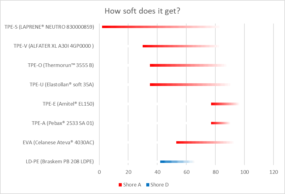
The members of the TPE-S family offer the best flexibility. TPE-O and TPE-U came to a bit closer to TPE-V than I had expected. TPE-E and TPE-A are clearly on a different level.
Please note that Shore D values are used in the case of LD-PE. Shore D 42 corresponds approximately to Shore A 82. Here you can find a useful comparison chart for the conversion between Shore A and Shore D. Due to the differences in the testing procedure and the material characteristics, however, components with a hardness of Shore A 85 and Shore D 40 might have very different touch and feel.
Components with a hardness of Shore A 35 and less are very flexible. They might not be able to carry their own weight and can be difficult to assemble.
At the other end of the scale, it is questionable if materials with hardness outside the Shore A scale, higher than Shore D 60, can be considered rubbery or even elastic.
Please remember that the elastomers creep just like any other plastics. If you stretch them for a longer period of time, they will not remember their original length and shape. Considerable stretching should be only temporary.
Softness/hardness is only one property to consider in the material selection process. Chemical resistance, UV-resistance, service temperature, etc. must be taken into account as well. Plasticprop.com can hopefully help you in this.
Thank you Jenni Ahola for your great help with the material search.
A phenomenon called hydrolysis degrades certain plastic materials and affects their mechanical properties.
This does not apply to all plastics. The polymer structure of the material must have an -OH group in it. Quite many do. Hydrolysis must be considered with (at least) the following plastics:
- Polyesters PBT, PET, copolyester, PLA
- Polycarbonate PC
- Polyurethane PU, TPE-U
- Polyamides like PA6, PA66, PA12 (Please notice that the common tendency of polyamides to absorb moisture is another thing)
- Polyacetal POM
As you can see, the majority of the common engineering materials are included. Should you be worried? Not really, as long as you take hydrolysis into account.
The phenomenon itself is not very aggressive. The key nominators (in addition to the required OH-group) are:
- Time. In short term use hydrolysis is hardly a problem.
- Temperature. The water must be hot; close to boiling or steam. Rain or splashes of cold water are not harmful.
Kitchen spatulas are typically made of PA66 and constantly sank in boiling water. At least mine are still in use after several years of use.
The scissor handles I wash on almost daily bases are made of PBT. No problems, although the water temperature in a consumer use dishwasher is typically not higher than 50°C.
How to avoid problems with design?
- Understand the service environment of the product. Will it be in prolonged contact with hot water or steam? Are you designing a rice cooker or a coffee machine?
- To play safe, prefer materials without the OH group.
- Try to find a reference case where the corresponding grade has been used successfully under similar conditions. Your material supplier can probably help with this.
The difference between amorphous and semi-crystalline plastic is something that every product designer should address. Here is what I find essential from a designer perspective
The difference in the thermal behavior
Amorphous and semi-crystalline plastics react to temperature in a different way. If we observe this closer, it will help us to understand the essential difference in their structure. This can be done in practice by heating some plastic items, for example, Plasticprop samples.
Let's have polystyrene PS as an example of amorphous plastic. Place the sample into an oven and start heating it slowly. If you take it out every 20°C (gloves recommended), you can notice that the sample gradually turns softer and softer. At 70°C the sample can already be bent quite easily. When the temperature of app. 95°C is reached, the sample totally (and more rapidly) loses its stiffness and collapses under its own weight. Polystyrene has reached its material-specific Glass Transition temperature (Tg). Amorphous plastic can only be used in temperatures below their Tg.
Semi-crystalline polymers have a partly different structure. A portion, of their polymer chains, 20-80% depending on the material, have arranged to tight and strictly orientated crystals. The remaining chains are in an amorphous state surrounding the crystals. Because of the amorphous part, semi-crystalline plastics do have a Tg as well.
Let's place a Plasticprop sample made of PA6 in the oven. At 50°C, it feels slightly more flexible than it did at room temperature. But if you take it out of the oven again at 60°C, the difference is bigger. PA6 has exceeded its Tg temperature, which is app. 55°C. The amorphous part of the polymer is now free to move but the crystals still hold the polymer structure together. The sample has turned from glassy to rubbery (or leathery) state. Semi-crystalline plastic can be used on both sides of its Tg, but the mechanical behavior of the material does not stay the same. Below Tg, in their glassy state, semi-crystalline plastics are stiffer and stronger but at the same time more brittle. Many semi-crystalline polymers are above their Tg in the room temperature (POM, Tg app. -60 °C; HD-PE, Tg -110°C, both approximately).
Elevating the temperature further will lead to a gradual decrease in modulus and strength. At 200°C the sample feels interestingly similar to the Plasticprops sample of TPE-S (SEBS). When the temperature reaches 220°C, the crystals dissolute and the solid piece turns to low viscosity liquid. The PA6 sample has then reached its Melting Point, Tm.
In both cases, amorphous and semi-crystalline, the process is reversible. In the case of semi-crystalline polymers, the temperature at which the polymer chains have reordered as crystals during the cooling process is known as Crystallization Temperature, Tc. This is far above the service temperature of the material.
How to address this in my design?
As said, amorphous plastics can be used only below their Tg. But it is vital to understand that their mechanical properties do not remain the same through the whole service temperature area. The higher the temperature, the lower the strength and modulus of plastic. PMMA, for example, at 60°C has completely different mechanical characteristics as PMMA at 23°C. Many plastic manufacturers are quite optimistic about the service-temperature they provide in their material data-sheets. The given temperatures may be on the very edge of reaching the Tg. You need to be skeptical when reading the data-sheets and bear in mind that temperature has a great influence on the mechanical properties of any polymer.
When using semi-crystalline plastic you need to check if its Tg is within the service temperature of the product. If so, make sure (by testing and exploring reference samples) that your requirements are filled on both sides of the Tg. For example, the Tg of PP homopolymer is -10°C. The ductility of a water bucket in Scandinavian winter might be surprisingly low.
Transparency
Amorphous plastics are generally transparent. Crystals block the light, which makes semi-crystalline plastics opaque. PP-random-copolymer is the only semi-crystalline transparent material, although even at its best it is slightly milky. Some modified grades of PA6 are available as well, but they should be described as translucent rather than transparent.
How to address this in my design?
Amorphous plastics have their weaknesses that are explained later in this article. I might spoil your excitement, but those are related to chemical resistance, continuous stress and friction/wear. Amorphous plastics do not serve well in machine design purposes. Combining mechanical functions to your transparent component must not be done with too much optimism. Problems are likely to occur. PP-RC is often the safest choice.
Straightness and dimensional accuracy
During the crystallization, the polymer chains are packed very firmly into a small volume. A large number of amorphous polymer chains are compressed into one crystal block. Due to crystallization, the shrinkage of semicrystalline plastics is higher. In the case of amorphous plastics the shrinkage is closer to the influence of negative thermal expansion.
Furthermore, amorphous plastics shrink evenly in every direction. In the injection molding process, the crystals of semi-crystalline plastics are oriented in the direction of the flow. As a result, the shrinkage in the direction against the flow is higher than the shrinkage in the flow direction.
Due to higher and uneven shrinkage products that are made of semi-crystalline plastics tend to warp more. It is more challenging to produce them straight.
How to address this in my design?
It is easier to produce a straight and dimensionally accurate product using amorphous plastic. Due to the mechanical functions or service environment of the product it is, however, often safer to use semi-crystalline plastic.
Regardless of what plastic you use, the following basic rules should be applied:
- Component geometry: Uniform wall thickness, no deep wells (difficult to cool), large radius rather than sharp corners.
- Tooling: Efficient cooling, proper gate location. These are important topics you need to discuss with your tooling supplier.
Surface quality
Higher shrinkage of semi-crystalline plastics easily leads to more visible sink marks. The surface of semi-crystalline plastics also tends to be slightly oily. Amorphous plastics typically provide a dry and shiny surface appearance.
How to address this in my design?
Amorphous plastics are the right choice for visually demanding components such as Bluetooth loudspeakers or WiFi routers. If the product is challenged by harsh service environment or mechanical use, semi-crystalline plastics are a safer choice. PBT, PA6, and PA12, for example, do provide a nice shiny surface. If ribs etc. are properly designed thin enough (app 0,6x wall thickness) the sink marks are not evident.
Compounds of semi-crystalline and amorphous plastics, such as PBT/PC and ABS/PA, are also available. The idea of these is to combine the advantages of both amorphous and semi-crystalline plastics. Sometimes it works.
Paintability, printability, gluability
Amorphous plastics are usually easy to paint, print and glue. With semi-crystalline, it’s the opposite. The crystals for some reason repel chemical substances.
How to address this in my design?
Don’t take it as given that all plastic components would be easy to print, paint or glue.
The higher the level of crystallinity, the more challenging it is to get something to stick on the surface. If you try scratching the printed text on Plasticprop sample made of POM, you’ll notice that the text peels off quite easily. PBT is quite easy to print or even paint, although it is semi-crystalline.
Gluing is hardly a process for modern high volume manufacturing, snap joints should be preferred instead. The same goes for painting. Glossy colored surface can be achieved without secondary operations, although exterior car parts are today commonly painted PP+EPDM+talk. Outdoor components made of PC are lacquered with a UV protective silicate layer.
Chemical resistance
Chemicals challenge every plastic product, especially together with elevated temperature and continuous load. In general, semi-crystalline plastics endure different chemicals considerably better than amorphous plastics.
How to address this in my design?
Amorphous plastics suit well as covers for electronic appliances, toys or picture frames. But in chemically demanding service conditions that include oil, petrol or strong cleaning detergents, etc, the use of semi-crystalline plastic should be required rather than recommended. If you are uncertain, semi-crystalline plastic is always a safer choice.
Resistance against continuous stress
Stress-cracking due to continuous load is the most common reason for plastic products to fail. The long-term load can be also cyclic, fatigue is another common reason for failures. Semi-crystalline plastics endure these both much better than amorphous plastics.
How to address this in my design?
If your component subjected to continuous or cyclic load, semi-crystalline plastic is a better choice. But this is not enough. You should also keep the long term stress level considerably lower (1/5 is a good starting point) that the short term data would suggest. If you must use amorphous plastic, the difference should be even higher. This is not "over-engineering", it is the most efficient way to prevent failures in the long term use.
Friction and wear
As said earlier in this article, the surface of semi-crystalline plastics is slightly oily. This gives a good indication of their bearing properties. The friction coefficient of semi-crystalline plastics is smaller than that of amorphous. They also resist wear better.
How to address this in my design?
Lower friction and better wear resistance are another two good reasons to favor semi-crystalline plastics in mechanisms and machine design applications.
SLS 3D printing is a common method for prototyping. The material used in SLS sintering is PA12. If you end up using amorphous plastic, the friction between the moving parts of the final product may be totally different than what you experienced with your 3D-printed models.